
A copper shielding braid should reach a connector through a defined shield-contact and grounding arrangement. The EMI shielding braided layer is made by intertwining bare or tinned copper wires around conductors. It forms a conductive layer around the cable’s internal conductors; the transition at the connector needs to carry that shielding function into the intended assembly design.
A braided layer is a flexible shielding layer and is easier to ground when a cable is crimped to a connector. This makes the cable end an important design location. Select the braid and the connector transition together, instead of treating a sleeve over the cable as the end of the shielding decision.
Carry the shield path to the connector
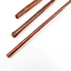
A conductive shielding layer around conductors reflects interference and provides a path for noise toward ground. The surrounding layer and the intended path both matter. A braid ending beside a connector without a defined connection leaves the designer with an unanswered transition question.
Trace the intended path on the assembly drawing: from the cable braid, through its chosen contact arrangement, into the relevant connector or equipment grounding provision. The drawing should identify what actually makes electrical contact, rather than relying on the appearance of a metallic shell.
This is the practical value of considering a braided shield at the cable-design stage. Its surrounding conductive structure can be connected to the intended grounding arrangement as part of the assembly. The braid, connector and equipment interface can then be evaluated together against the electrical requirement.
Keep conductors and shield contact distinct
The braid surrounds the conductors; it does not replace their insulation or their signal and power contacts. Keep those roles separate when the cable opens into the connector termination area.
An exposed braid strand near a conductor contact is not useful merely because both belong to the same cable. Define how the shielding layer is gathered or retained by the selected termination arrangement, and how the insulated conductors reach their own contacts.
This separation makes the transition easier to review. The engineer can identify the intended electrical paths without confusing a shield-contact feature with a conductor terminal. It also gives production a clearer assembly target than an instruction to “ground the braid” without a mating detail.
The connector design controls which shield-contact provisions are available. Use its applicable assembly instructions for that interface; a generic braid photograph is not a termination instruction.
A flexible braid still needs an orderly transition
The braided wire construction provides a flexible surrounding layer along the cable. At the connector, however, the material must leave that cable-run arrangement and meet the chosen contact provision.
Think about where that transition begins, how much braid is exposed and where movement occurs relative to the contact area. A cable that moves near the connector should be reviewed in its intended assembled condition, including the support arrangement around the cable end.
These details help the designer retain the purpose of the flexible shield without treating the electrical contact as a free-moving section of braid. They also make an installation trial more informative: the trial can show the actual transition rather than a loose copper sleeve placed near unrelated hardware.
Avoid assigning a universal exposed length or a grounding method to every braid. The correct arrangement depends on the connector and the equipment’s electrical design.
Separate strain support from the electrical contact
Mechanical retention and shielding contact are different functions. A cable clamp may support the assembly, but that alone does not define the intended electrical path from the braid. Similarly, a shield contact should be considered within the complete mechanical design instead of being assumed to carry every cable pull or movement load.
Mark both functions on the drawing. Where a component is intended to perform both, its design and assembly instructions should establish that role. Where separate features perform them, keep their positions and responsibilities clear.
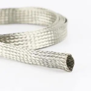
The open braid end and the interwoven wire structure show why handling matters at this transition. The product is a woven conductive layer with individual wires; its appearance is different from a solid connector shell. A clear mating arrangement connects those two structures deliberately.
Evaluate the completed connection
Use a completed cable/connector sample for the electrical assessment. Define the intended grounding scheme and relevant operating conditions before interpreting a measurement. A basic continuity observation can answer one contact question, but it does not by itself establish the assembly’s shielding effectiveness.
The braid has small air gaps between copper wires and does not provide full surface coverage. Coverage describes the construction; the connected assembly still needs to meet its own electrical requirements. Keep any measurement result attached to the tested arrangement rather than to the braid family in general.
If the connector, movement or grounding scheme changes, discuss a customised configuration using the revised drawing and acceptance conditions. This is a design review of the specific transition, rather than a universal instruction to connect every shield in the same way.
FAQ
Does touching a metal connector shell establish the intended ground path?
Do not infer the connection from appearance. Identify the designed shield-contact provision and evaluate the completed electrical path using the applicable connector and equipment requirements.
Should every cable shield be grounded at both ends?
There is no universal grounding instruction for every system. Follow the equipment’s electrical design and assess the chosen cable/connector arrangement under its operating conditions.
Is cable strain support the same as a shield contact?
They serve different functions. Specify mechanical retention and the intended conductive contact separately, or use a component whose design explicitly provides both.
Request a Shield-Transition Review
Provide Bonsing with the cable cross-section, selected braid, connector drawing, intended grounding scheme, movement and strain-support arrangement, and electrical acceptance conditions. Request a shield-transition review to discuss the EMI shielding braided layer within the proposed cable assembly.
Post time: Oct-23-2026