
The EMI shielding braided layer is made by intertwining bare or tinned copper wires around conductors. It places a conductive textile-like layer around the cable’s inner conductors. Its value in a design depends on how that surrounding layer participates in the interference path affecting the circuit.
Electrical noise can travel through power or signal cables or through space as electromagnetic waves. The stated braid coverage range is 70% to 95%, depending on weave tightness and configuration. That range describes the braid construction; the first selection question is still which noise path the proposed shield must address.
Locate the noise path before changing the cable
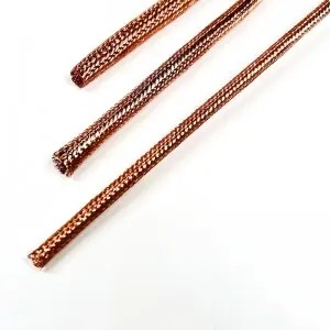
Start with the affected circuit and the condition under which the disturbance appears. A problem that occurs when nearby equipment switches may involve a different path from a disturbance entering through a shared power or signal connection. The observation helps define an investigation; it does not establish the cause by itself.
Identifying the path gives a braid enquiry a concrete purpose. It allows the engineer to explain where the cable is exposed, how it connects to the equipment and which response needs to be evaluated. An otherwise well-made shield is difficult to assess when the requirement is only “remove noise.”
What a surrounding copper braid contributes
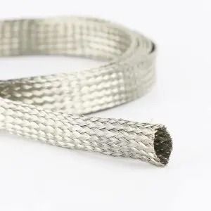
A conductive shielding layer around conductors reflects interference and provides a path for noise toward ground. The layer therefore has a role within an electrical arrangement, rather than merely adding a protective outer covering.
The copper wires form a flexible surrounding braid. This makes the construction relevant when the cable needs a conductive layer along its route. The engineer can consider that layer together with the cable design and its intended conductive connections, instead of expecting an unrelated external sleeve to perform the same electrical function.
Use an image of the braid to recognise the procurement object and its place around the conductors. It is construction evidence, not a visual measurement of how much interference a completed system will reject.
Separate interference around the cable from disturbance carried on a conductor
Interference can couple to a cable from its surroundings. A disturbance can also enter the circuit through an electrical connection or already be present on a conductor. Those descriptions may involve related mechanisms within one installation, so they should guide a path investigation rather than become a rigid two-category diagnosis.
| Observed or suspected path | Question for the engineering review |
|---|---|
| Coupling from the surrounding environment | Which cable segment is exposed, and how is its conductive surrounding layer arranged? |
| Disturbance arriving through a power or signal connection | Where does it enter the circuit, and what equipment/interface requirements address that path? |
| Disturbance associated with a changed route or connection | What changed in the cable arrangement, and which operating condition reproduces it? |
This distinction helps prevent the team from changing braid construction repeatedly when the relevant path also involves another connection or equipment function. Conversely, an external coupling concern gives the surrounding shield a specific role to investigate.
Follow the shield path through the cable arrangement
A surrounding conductive layer needs to be considered with the intended connections at the cable interfaces. Review the selected braid, cable route and grounding arrangement together with the responsible electrical design. The visible braid alone does not reveal the complete conductive path through the equipment.
Keep mechanical support and the electrical shield connection identifiable in that review. A change to a connector, route or equipment interface may change the path being evaluated even when the braid itself remains the same. Retaining those conditions makes a later comparison understandable without prescribing a universal grounding method.
Compare a defined system condition
Define the operating condition and response that the electrical team needs to compare. Retain the cable, braid, route, connection arrangement and relevant equipment state. Change one clearly named variable where the evaluation method allows, and record other changes that affect interpretation.
Evaluate the completed arrangement using the applicable engineering procedure. If the requirement points to a different interface or additional electrical measure, take that finding into the system review. Discuss a customised braid configuration with the identified cable and coupling inputs when the surrounding layer is the part that needs to change.
FAQ
Can shielding braid solve every noise problem on a cable?
No. Identify how the disturbance reaches the circuit. The surrounding braid must be evaluated as part of that path and the complete cable/equipment arrangement.
Is a disturbance on a power conductor the same as radiated pickup?
They describe different possible paths into a circuit, although mechanisms can interact within an installation. Investigate the actual entry and coupling arrangement before deciding what to change.
Does braid coverage tell me which noise path is present?
No. Coverage describes the braid construction. Path identification depends on the circuit, connections, exposure and operating observations.
Discuss a Cable Noise-Path Review
Start with the EMI shielding braided layer construction. Provide the affected signal or power circuit, disturbance conditions, suspected coupling path, cable route and grounding arrangement. Discuss a cable noise-path review with Bonsing to define the relevant braid configuration questions within the wider electrical design.
Post time: Nov-06-2026