
The EMI shielding braided layer is made by intertwining bare or tinned copper wires around conductors. It provides a conductive surrounding layer for a cable design while retaining the flexibility of a braid. The stated braid coverage range is 70% to 95%, depending on weave tightness and configuration. Use that percentage to describe the construction you are comparing.
Coverage and shielding effectiveness answer different questions. Coverage describes how much of the surface the weave covers; shielding effectiveness concerns the electrical behaviour under defined measurement conditions. Keeping the two separate allows a cable engineer to specify a braid construction and then choose an acceptance evaluation for the finished assembly.
What coverage describes
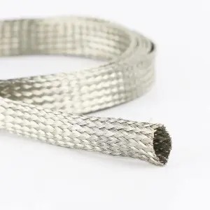
The braid has small air gaps between copper wires and does not provide full surface coverage. The visible wire pattern therefore matters: tighter and more open constructions present different proportions of wire and gaps around the conductors.
The coverage percentage is useful on a construction drawing or in a configuration comparison. It gives the supplier and cable designer a common description of the weave requirement. Braid coverage is a construction measure; it is not a tested shielding-effectiveness result for a complete cable assembly.
| Question | Relevant information | Decision it supports |
|---|---|---|
| What braid is being specified? | Wire material, weave and coverage configuration | Construction comparison |
| How does it connect to the rest of the cable? | Conductor arrangement and connector/grounding interface | Assembly design |
| How does the assembly perform in its intended environment? | Defined noise conditions and electrical acceptance method | Performance evaluation |
Product and Specification Reference: EMI shielding braided layer; Bonsing public product-detail page, checked in August 2026. The 70%–95% range is configuration-dependent braid coverage, rather than a shielding-effectiveness result. Review the requested weave and assembled-cable requirement before specification use.
Why the braid remains flexible
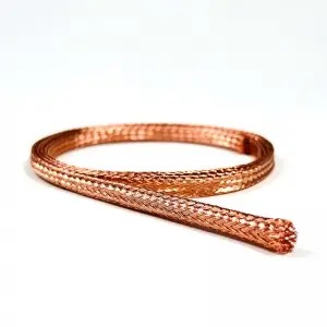
Interwoven copper wires form a conductive layer that can follow a cable’s shape. For a routed cable, that makes the braid a construction worth evaluating where the shielding layer needs to move with the assembly. The relevant task is the cable’s actual route and handling requirement, rather than a promise of a particular bend radius or flex life.
Compare the proposed braid on the intended conductor or cable geometry. A percentage on a drawing provides construction information, while a representative assembly shows the wire pattern in the form that will be handled. Retain that geometry in the evaluation so a later construction change can be reviewed against the same route.
Follow the conductive path to the connector
Electrical noise can reach a design through its cables or through space. A conductive layer around the conductors reflects interference and provides a route for noise toward ground. This gives the braid a defined role in the cable design, but the route continues beyond the isolated sleeve sample.
A flexible braid is easier to ground when the cable is crimped to a connector. For the engineer, the useful next question is how the proposed shielding layer meets the actual connector and grounding arrangement. Include that interface in the assembly discussion so the cable covering and its end connection are considered together.
An attractive braid photograph or a high coverage number leaves that interface unanswered. Evaluating the cable with its intended connector provides a more relevant basis for the electrical acceptance task, without imposing an unverified termination recipe.
Compare assemblies rather than percentages alone
If two proposed constructions have different coverage, retain their full assembly descriptions. Keep the conductor geometry, connector arrangement and acceptance conditions visible beside the percentages. Otherwise the comparison may attribute an assembly difference to coverage alone.
Define the noise environment and the result the buyer needs to assess. Where electrical acceptance is required, use an agreed method for the complete assembly under those conditions. Do not convert a coverage percentage into a dB value or a percentage of noise removed.
If the desired route or electrical requirement calls for a different construction, discuss a customised shielding configuration with Bonsing. Bring the connector arrangement and acceptance requirement to that discussion so the option can be evaluated as part of a cable design.
FAQ
Does 95% braid coverage mean 95% noise reduction?
No. Coverage measures the weave’s surface coverage. Noise reduction requires an electrical assessment under defined assembly and measurement conditions.
Can I choose a braid from coverage without considering termination?
Coverage helps describe the construction, but the connector and grounding arrangement belong in the assembly review and performance evaluation.
Does an EMI braid completely cover the cable surface?
No. The braid retains small air gaps between copper wires. The stated 70%–95% range depends on weave tightness and configuration.
Request a Shield Construction Review
Share the conductor or cable geometry, proposed coverage, connector and grounding arrangement, route requirements and electrical acceptance conditions. Review the EMI shielding braid construction, then request a shield construction discussion tied to the assembly you plan to evaluate.
Post time: Oct-16-2026